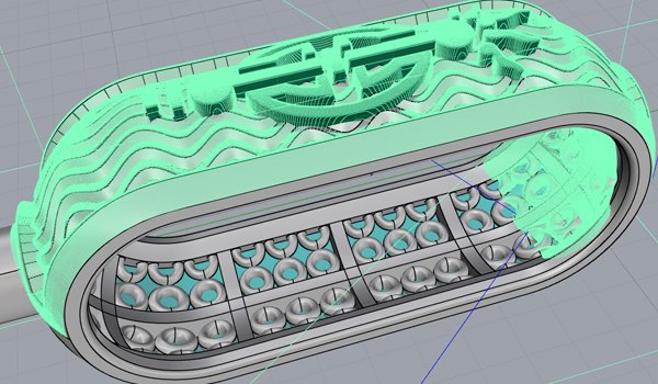
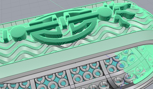
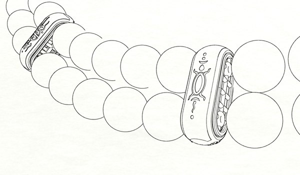
Search

From Concept to Realization

Jewelry designers use CAD to give life to their ideas in the form of 3D models for the ultimate in design and creativity! Ideas are given form when they are milled from a raw wax work-piece, and then cast into precious metals and set with dazzling stones!

Necklace by Raims

CAD – Computer-Aided Design

CREATING NECKLACE WITH PEARLS BY RAIMS

After having discussed with the customer the general idea of their project based on budget, size, timing, materials, and design, a preliminary pencil sketch begins to materialize on paper. Further work is transferred to the computer in a CAD program for three-dimensional modelling. In this example, we use Rhino 3D. A three dimensional model of all elements of the necklace is created, as well as a general model of the whole structure with the exact size and number of pearls

Sketch
3D CAD Design
3D Rendered Model

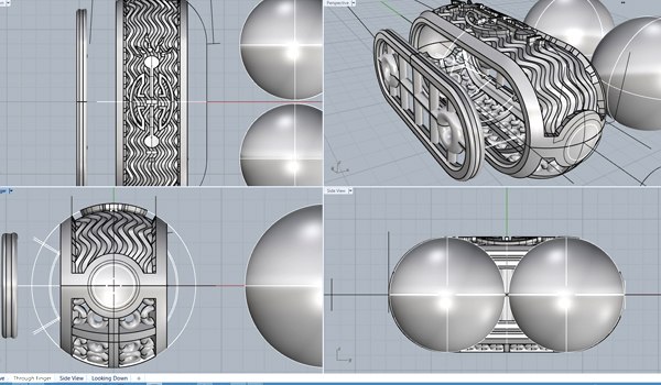
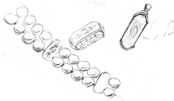
In the design program, in this case Rhino 3D, designers can see the project from different angles. Parts can be adjusted to fit together smoothly, allowing for alternate options and scaling to the clients’ needs.

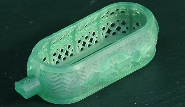
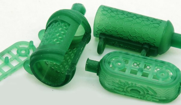
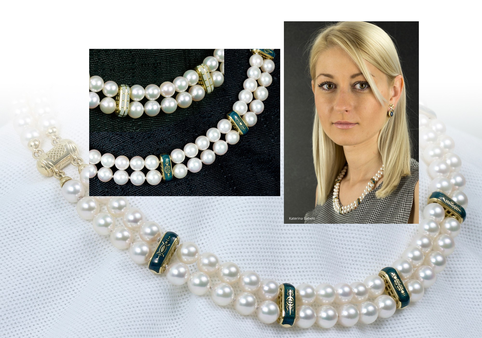
A completed 3D model can be used in two ways. First, the manufacturing of the product, in which the next step would involve calculating CNC information in the CAM program. The second is a render of the model into a lifelike image to show to clients or to market your designs and services. At the bottom of this section, you can see a good example of a rendered image. This is not a photo of the actual product, it’s a virtual necklace, sitting on a virtual black pedestal.

СAM – Computer-Aided Manufacturing

After a design is created in a CAD program, it is transferred to the three-dimensional work space of the CAM program or module. CAM programs differ greatly from each other, depending on the type of CNC/milling machine they’re intended for. The most basic CAM software options will only work with 3-axis machines. The most complex options can drive a 5-axis mill, such as the Mira Mill. They require a powerful computer and certain skills from the user.

How to work with CAM program based on Rhino3D

The virtual model of each piece of jewelry is first placed at the 0(origin) of all axes in the CAD program. It’s oriented to match the real-world setup of the mill, and is ready for the CAM program to read its surface. The CAM program also has to be configured for the CNC mill you will be using, followed by the sizes and shapes of cutting bits. Accurate calculations require an understanding of how the mill behaves in real life, and the operator’s preferences. The nature of the model is taken into account, and the appropriate strategy is chosen. This means moving the model around for maximum exposure to the cutting tool. The calculations themselves are all performed automatically by the computer. When this is done, the machine is given commands to move the axes and cutting tools. Getting the right strategy in place for maximum exposure to the cutting tool can take practice, but it will mean less post production work. In these pictures, the light green lines represent the path the cutting tool will take across the model. These tool-paths are converted into a basic set of instructions for the CNC mill, which will then move the cutting tool to follow these tool paths. This basic set of instructions are called G-codes.

CAM Toolpath Lines
Wax Molds

СNC – Computer Numerical Control

When CAM files are prepared properly with accurate G-codes and the mill is loaded with a properly prepared blank wax, milling isn’t complicated. Cutting the wax model on the machine is one of the most important stages of the modern CAD model for production. Models are created in the virtual world, but to be useful they need to be real and tangible. At this stage, the designer’s fantasy comes to life. From a plain unprocessed piece of green wax, an elegant model with microscopic details and the finest surfaces is born. If earlier generations created the master models by hand with chisels, and files, the new generation’s hands need only master the computer mouse and a grid on the screen.

The machine will alternate cutting each side of the wax to maintain stability and brings the computer model to life. Setting up your machine to run the job is a straight-forward procedure: Power up the equipment, move the spindle to its home position, mount your wax work-piece into a fixture, and attach the fixture to the mill. Next you will need to load the tool paths (G-code) from your design software into the CNC control computer. Depending on the model and how fast you are running the machine, you may need to turn on the lubricant jet, which squirts a small amount of lubricant fluid onto the work-piece, right where the milling bit is working. This is one of the most exciting parts of the process, where you get to see your idea come to life.

Post-Processing

Once your models have been milled, you will be able to re-work any parts you feel might need to be modified. You also may want to assemble some multi-part wax models before casting, using your best judgment and experience.

Overview of the casting process

The wax model(s) are sprued and fused onto a rubber base, called a “sprue base”. Then a metal flask, which resembles a short length of steel pipe that ranges roughly from 1.5 to 6 inches tall and wide, is put over the sprue base and the waxes. Most sprue bases have a circular rim which grips the standard-sized flask, holding it in place.

Investment (refractory plaster) is mixed and poured into the flask, filling it. It is allowed to harden, and then the investment flask is placed cup-down in a kiln, whose heat hardens the plaster into a shell, and the wax melts and runs out. The melted wax can be recovered and reused, although it is often simply burned up. Now all that remains of the original artwork is the negative space formerly occupied by the wax, inside the hardened plaster shell. The feeder, vent tubes, and cup are also now hollow.

Casting is usually done straight from the kiln either by centrifugal casting or vacuum casting.

Gold Cast Parts
Enamel Applications

The Finished Masterpiece

The design of this necklace is quite unique. Each metal element has two completely different patterns on both sides. One with a guilloche area covered with blue enamel. The second – with a translucent design, white enamel. Thus, the necklace can be worn on both sides, in dark blue or light versions. All gold items are very light and hollow. They have closed side patterned covers.

To prevent damage to the thinnest layers of enamel, there is no soldering or laser welding involved. Another design complexity is still in the selection and linking the thread pearl necklace that all lay on the bust level. The product is no less unique in its lock design. It appears solid and easy to open, while also being durable and reliable. This necklace was made complete with earrings in this same style. This entire set was made solely by Raims from the idea to the finished product.